Mission Background
Many ESA missions, past, present and future rely on parachutes for their operation. Examples include the Huygens mission to Titan, the ExoMars missions to Mars and the Space Rider space plane.
Although ESA employs many engineers who are experts in their fields, the use of parachutes for space missions is not sufficiently common to justify the existence of a permanent team of parachute engineers with in-house developed software tools.
Customer Requirements
ESA required a Parachute Engineering Tool to enable their engineers to carry out systems engineering of parachute systems, system studies in the ESA Concurrent Design Facility (CDF) environment and a means of checking calculations produced by their industrial contractors. The tool had to include modules to perform all the common system design tasks for parachutes from the choice of parachute type, through sizing and stressing of the parachute to performance prediction for the completed system.
Our Work
Working with SCISYS, the Parachute Engineering Tool is a software toolbox which provides modules to perform all the common parachute engineering tasks throughout the design process of a space mission (or indeed any system utilising parachutes). An open architecture has been applied so that new tools can be added as and when required.
Parachute Engineering Tool
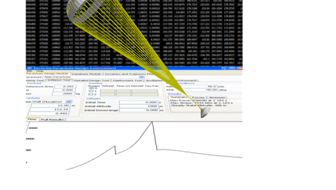
All the modules are integrated within a Graphical User Interface which allows them to be run individually and to pass data between them for different phases of the analysis.
The models are validated against mission data (e.g. Huygens and ExoMars) and Technology Research Programmes (e.g. Supersonic Parachute Research and SUPERMAX).
A complete list of modules is set out below:
Parachute Type Recommendation
This module recommends a parachute type (e.g. Disk-Gap-Band or Ringslot) for a given mission based on the requirements for the system and the environment in which it operates.
Parachute Sizing
This module will calculate the size of parachute required for a mission based on system parameters such as the required terminal rate of descent. The tool makes use of an extensive database of parachute types built into the software to obtain the characteristics of the chosen parachute type.
Parachute Inflation
The highest load experienced by a parachute is usually the inflation force. In order to design an optimal, low mass system it is necessary to calculate this force which varies with deployment conditions, payload design and the environment. The inflation tool enables calculation of parachute inflation in terrestrial tests and allows extrapolation to planetary conditions. It is validated against over 30 years of test data gathered by Vorticity and others.
Material Selection
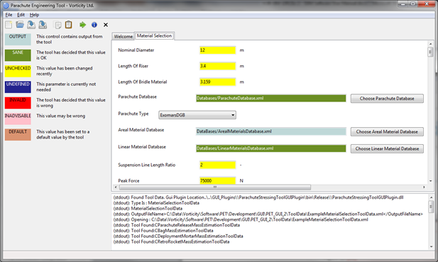
Once the parachute type, size and inflation load have been determined, the detailed design and materials may be selected. For any parachute design, there are always several options using different materials and detailed geometry (e.g. the number of lines). This tool recommends a detailed design and materials based on the operating conditions and chosen margin policy. It then allows the user to fine-tune the design. The mass of the final parachute is then calculated taking into account factors such as seaming allowances.
Parachute Deployment
Deployment is the most challenging phase of a parachutes life cycle. It must be deployed in a controlled progressive manner, ensuring full deployment without risking excessive deployment speeds. Parachutes can be deployed by mortars, tractor rockets or pilot chutes. The deployment model allows all these methods to be modelled and optimised to obtain the best solution for any mission.
Trajectory Tool
A trajectory tool is included to allow the performance of the parachute system to be assessed against mission requirements for total distance covered, flight time and verticalisation of the system.
Stability Tool
A stability tool is included to model the motion of the parachute / payload system with 6 degrees of freedom for each (position and orientation). This allows the response of the system to external influences such as wind gusts to be identified.
Ancillary Mass Estimation
A parachute system will always include many components in addition to the parachute itself; for example, deployment systems, release devices and containers and bags to pack the parachute(s). In order to optimise the whole system, these components must be taken into account. This tool allows estimation of the mass of all these components.


